By reading and attempting this tutorial you agree to terms that hold you completely responsible to injuries and damages to people, animals, objects of autonomous/robotic life and/or material possessions, that may occur by following this, Famicom-NES Controller Mod, tutorial.
By accepting these terms you will not hold the author liable for such damages stated above.
Attempt at your own risk.
This mod will assist in transforming your Famicom's hard-wired controllers into the American N.E.S. (Detachable) Controller.
Mod difficulty: Advanced
Required tools:
1. Soldering Iron (fine tip).
2. Solder.
3. Solder Sucker/ Desoldering pump and Desolding Braid.
4. Wire Strippers.
5. Phillips Screwdrivers (Various Sizes)
6. Small needle-nose pliers.
7. Hot Glue Gun.
8. Electrical Tape/Shrink.
9. Razor Blade.
10. Sandpaper.
Optional tools:
1. Tweezers.
2. Dremel
Parts Needed:
Parts Needed:
1. Cable/Wire
2. N.E.S. controller ports.
2. N.E.S. controller ports.
--------------------------
Step One: Desolding The Four Score
Tools Needed:
1. Solding Iron.
2. Solder Sucker and Desolding Braid.
3. A Lot of Patience.
-----
The first course of action is to find 1 of 2 items, 1. A Four Score multi-tap adapter or 2. A broken N.E.S.system.
I suggest buying a Four Score since there are 4 connectors and they are cheaper.
Side Notes:
Alternatively you may wire up the Four Score to a Neo Geo/ Famicom Extension cable.
This entails cutting the Four Score's original cable off and then cutting a lot of leads on the board itself and then wiring the controller ports individually to the Extension cable.
The upside is that you don't have to hack your Famicom's shell for controller port placement.
The downside: You will lose turbo functionality of the Four Score, however that's going to be gone regardless.
After procuring a Four Score (or broken NES system) you will want to dismantle this beast via the five screws on the back and then, further, removing the PCB screws.
At this point you may cut the cord of the Four Score (closest to the PCB) off.
Using your soldering iron and solder sucker carfully remove the NES controller ports from the PCB.
Ensure to take your time and do not heat the pins holding the NES ports to the PCB too much as they will melt the plastic and push through.
Remember. These pins are needed as they are what we are going to solder wires to later on in this build.
Use the solder sucker; remove as much solder as possible.
The Desolding Braid may be used to clean off any remaining solder left behind.
Once you have removed all the solder from all (28) pins it's time to gently lift the NES connectors away from the PCB.
Unless you plan to use the PCB for another project then don't worry to much about it cracking or breaking leads.
The most important part is removing the NES connectors intact.


====================
Step 2: N.E.S. Connector Wiring
Tools Needed:
1. Soldering Iron.
2. Solder.
3. Wire Strippers.
----
ATTENTION:
If you are planning to place your NES connectors in a different location other than the front of the Famicom then skip to Step 3 before proceeding on with Step 2.
---------------
Now that we have the NES connectors free we will utilize the wire the Four Score has to offer.
Side Note:
This mod removes the Ejector Lever to make room for the controller wires to reach their solder positions.
My cable harnesses were about 6-7 inches (15.24cm-17.78cm) in length.
There are a few alternate routes as to how you can run the cables/wires, so determine how you want to route the cable before cutting.
1. Cut two lengths of cable off the cord that belonged to the Four Score and strip 1-2 inches (2.54cm-5.08cm) of the black outer jacket away from both ends (The white string within may be removed as this is just filler).
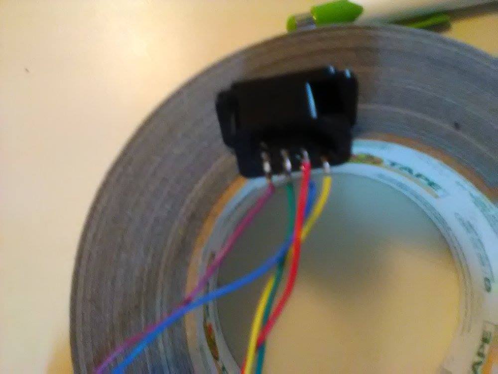
2. Strip each colored wire 1/8th inch (0.3175cm) and tin the tips.
If you are keeping with the standard Famicom/NES wire colors use the photo below.
(Yes. You can wire up a SNES controller port to the Famicom as well.)

Please note that this photo shows only Player 1's Wire Configuration where pins 1-5 are the only ones used. Pins 6 and 7 are only used by Player 2.
UPDATE: 06/16/2017

UPDATE: 06/16/2017

-----
Below is the wiring diagram for Player 2.

Using the above Photos; Solder your colored wires to the pins on the back of the NES controller ports. Remember that Player 2 will use all (1-7) pins, whereas Player 1 will only use 1-5 pins
====================
Step 3: Case Modification
Tools Needed:
1. Phillips Screwdriver.
2. Razor Blade.
2. Razor Blade.
3. Needle nose pliers.
4. Sand Paper.
5. Sharpie/Pen/Pencil.
6. Dremel (Optional).
From this point we change pace a little by switching over to the Famicom System.
1. Dismantle the Famicom completely.
I mean take everything out of the plastic shell and set all of the important parts aside in a nice safe place.
2. Decide where you want your new controller ports to be and mark them out using a sharpie/pen/pencil.
3. Being ever so careful: begin to cut away the plastic so that your NES connectors have a nice, snug, opening to rest within.
Using needle nose pliers makes it easy to carefully remove tabs and smaller pieces of plastic once scored by the razor. Also. Don't forget to smooth down those rough and sharp edges with some fine grit sandpaper.
Using needle nose pliers makes it easy to carefully remove tabs and smaller pieces of plastic once scored by the razor. Also. Don't forget to smooth down those rough and sharp edges with some fine grit sandpaper.
Side Note:
The NES connector ports have little tabs on both sides that are perfect for overlapping the Famicom housing, either on the inside or the outside will work.
The NES connector ports have little tabs on both sides that are perfect for overlapping the Famicom housing, either on the inside or the outside will work.
Be sure to check the holes frequently using the NES connectors for that snug fit feel and alignment..
Remember that you can always take away more material if needed, but you can't put it back once it's gone.
4. Dry run the NES connectors with all the hardware re-inserted to ensure a good fit on all fronts.


====================
Step 4: N.E.S. Connectors to the Famicom.
Tools Needed:
1. Soldering Iron
2. Solder.
3. Tweezers (optional)
ADVISORY.
I highly recommend wiring Player 1 connector into the Famicom's Player 1 socket.
This is a tried and true method to ensure the highest game compatibility.
I am only recommending this because I have seen a lot of sites misleading the public by having them solder player 1 onto the EXT port. Which I can say does not work for a lot of games. The controller simply won't work.
-----
Now that we have a placement for our NES connectors lets wire them onto the PCB.
Starting with Player 2 controller lets have a look at how to hook this bad boy up.

The photo below is a reference as to where you will be soldering in the Player 2 controller.
(Colored wires may vary)

All the legwork has been done for you so reference the NES connector pin-out pictures from Step 2 to the Famicom EXT pin-out in this step for player 2.
----
Connecting Player 1 to the Famicom Player 1 Socket is a cinch.

You have 1 of 2 options for this connection.
WARNING.
Option 1 below means ruining your Famicom's Player 1 controller.
1. Cut off the Connector (leaving at least 2 inches / 2.54cm) on the Famicom Player 1 controller cable and splice the NES connector into them (remembering to switch the RED and YELLOW wires).
Solder them together and, using electrical tape/shrink over the bare wires, plug Player 1 directly into the socket on the Famicom's PCB.
2. Simply solder the NES connector wires onto the PCB (remember to switch the RED and YELLOW wires)
Below is a photo of the wiring configuration between a NES and Famicom controller.
As we can see (Player 1) PCB and design is a perfect replica and a NES PCB fits perfectly into a Famicom Player 1 Housing.
However. Player 2's PCB is a mirror image and is not compatible with NES PCBs, also there are no START/PAUSE button slots on the Famicom Player 2 controller housing.
Now that we have a placement for our NES connectors lets wire them onto the PCB.
Starting with Player 2 controller lets have a look at how to hook this bad boy up.
The diagram below is of the Famicom EXT pin-out from bottom of the PCB when the Famicom's front is facing you (Also See photo 2 below).

Side Note:
The 'SHARED' connections are used for both Player 1 and Player 2.
However. As I have stated above; we are not connecting Player 1 to the EXT.
The photo below is a reference as to where you will be soldering in the Player 2 controller.
(Colored wires may vary)

All the legwork has been done for you so reference the NES connector pin-out pictures from Step 2 to the Famicom EXT pin-out in this step for player 2.
----
Connecting Player 1 to the Famicom Player 1 Socket is a cinch.

You have 1 of 2 options for this connection.
WARNING.
Option 1 below means ruining your Famicom's Player 1 controller.
1. Cut off the Connector (leaving at least 2 inches / 2.54cm) on the Famicom Player 1 controller cable and splice the NES connector into them (remembering to switch the RED and YELLOW wires).
Solder them together and, using electrical tape/shrink over the bare wires, plug Player 1 directly into the socket on the Famicom's PCB.
2. Simply solder the NES connector wires onto the PCB (remember to switch the RED and YELLOW wires)
Below is a photo of the wiring configuration between a NES and Famicom controller.
As we can see (Player 1) PCB and design is a perfect replica and a NES PCB fits perfectly into a Famicom Player 1 Housing.
However. Player 2's PCB is a mirror image and is not compatible with NES PCBs, also there are no START/PAUSE button slots on the Famicom Player 2 controller housing.

Side Note:
Don't bother trying to modify a Famicom 2 controller as it involves a lot of cutting away of the plastic and 2 of the screw mounts are off-set from a NES's controller, making it impossible to fully secure the inner workings of the controller.
At this point you may want to test your controller connections by inserting a game that supports 2 players (I recommend Super Mario/Duck Hunt 2-in-1 cart).If you are lucky enough to have a Zapper then Duck Hunt is the perfect test cart.
Side Note:
In order to play any light gun/Zapper games you will need an old CRT television.
Today's televisions do not support the strobe effect needed for these old light gun/zapper games.
Start up your 2 player game and select 2 players.
Mess around with Player 1's functions, pressing all the buttons, to ensure you have a good setup.
Purposefully die so that you can now do the same with the Player 2 controller.
Switch over to a light gun/zapper game and make sure it works properly also.
Side Note:
Some games (Such as Super Mario Bros.) does not support Pause on the Second player controller.
So don't worry if you are mashing PAUSE/START on controller 2 and nothing is happening.
As long as the D-Pad and B, A buttons work you should be in good shape.
Also:
If you don't have a zapper or light gun game to test, don't worry.
If the second player (on whatever game you tested) plays normally you should be fine for when/if you ever use the zapper.
If everything works as intended then it's time to move on to the next step.
-----
Troubleshooting.
If any of the controllers don't work as intended (and defects within the controller are completely ruled out) then a wire might have gotten crossed (such as Clock and/or D3/4) or there could be a short within the connections. Make certain that all connection points (where you soldered) are not touching any other leads.
-----
====================

Step 5: Securing the N.E.S. connectors.
Tools Needed:
1. Hot Glue Gun
2. Razor Blade
3. Small mounting bracket and hardware (Optional)
-----
If you are going with the mounting bracket options then may I say the best of luck to you, as I am sure you have already planned out this course of actions and are adept.
For those of us that are inept, or perhaps we are just lazy and cheap (I know I am), but that doesn't mean we can't produce quality. We are going to use our hot glue gun and secure the NES connector ports into our newly modified Famicom case.
The best course of action I found was to use a bead of hot glue around the new opening and then quickly, but carefully, insert the NES connector into position.
Once the connector is in place fill in the gaps surrounding the NES connector and the Famicom housing/case to ensure a secure hold. As these connectors are now going to get a lot of use from pushing and tugging from those controllers being inserted and removed.
I took the liberty of securing the wires connected to the NES connectors but this is optional.

(Sorry for poor image quality)
Be sure to trim off any hot glue that may have leaked out; to give it that clean, factory, look.
==========
Step 6: Assembly
Tools Needed:
1. Phillips Screwdriver
-----
By this point you are done with the mod and can now assemble your Famicom,

==========
I hope this tutorial gave some insight into modding the Famicom controller ports.
Until Next Time.
~Geist von P.A.
====================
INTERMISSION:
Before we proceed I would like to take this moment to reflect on another person's modding through the use of Hot Glue.
This, ladies and gentlemen, is not standard practice for modding any electronics and is a disgrace to the modding community (IMO).
So don't go overboard with your hot glue.

We now return you to our regularly scheduled program.
====================Step 5: Securing the N.E.S. connectors.
Tools Needed:
1. Hot Glue Gun
2. Razor Blade
3. Small mounting bracket and hardware (Optional)
-----
If you are going with the mounting bracket options then may I say the best of luck to you, as I am sure you have already planned out this course of actions and are adept.
-----
ATTENTION:
Before laying any hot glue and securing your NES connectors into their respected holes; Remember to route your NES connector cables and ensure the Famicom PCB can be remounted and the whole unit can close correctly.
-----
For those of us that are inept, or perhaps we are just lazy and cheap (I know I am), but that doesn't mean we can't produce quality. We are going to use our hot glue gun and secure the NES connector ports into our newly modified Famicom case.
The best course of action I found was to use a bead of hot glue around the new opening and then quickly, but carefully, insert the NES connector into position.
Once the connector is in place fill in the gaps surrounding the NES connector and the Famicom housing/case to ensure a secure hold. As these connectors are now going to get a lot of use from pushing and tugging from those controllers being inserted and removed.
I took the liberty of securing the wires connected to the NES connectors but this is optional.

(Sorry for poor image quality)
Be sure to trim off any hot glue that may have leaked out; to give it that clean, factory, look.
==========
Step 6: Assembly
Tools Needed:
1. Phillips Screwdriver
-----
By this point you are done with the mod and can now assemble your Famicom,

==========
I hope this tutorial gave some insight into modding the Famicom controller ports.
Until Next Time.
~Geist von P.A.