By reading and attempting this tutorial you agree to terms that hold you completely responsible to injuries and damages to people, animals, objects of autonomous/robotic life and material possessions, that may occur by following this, Famicom A/V Mod II (Connector Installation), tutorial.
By accepting these terms you will not hold the author liable for such damages stated above.
Attempt at your own risk.
=================================
PREAMBLE:
This mod will assist in transforming your Famicom's AC/RF Module Composite Video to A/V (RCA Connector Installation).
|
ADVISORY:
This will completely remove the functionality of the Famicom's original RF.
----------
For a tutorial on converting your Famicom to A/V click HERE.
Mod difficulty: Advanced
Required tools:
1. Soldering Iron (fine tip).
2. Solder.
3. Solder Sucker/ Desoldering pump and Desolding Braid.
4. Wire Strippers.
5. Phillips Screwdrivers (Various Sizes)
6. Small needle-nose pliers.
7. Hot Glue Gun.
8. Electrical Tape/Shrink.
9. Razor Blade.
10. Sandpaper.
11. Metal Cutting Snips.
Optional tools:
1. Tweezers.
2. Dremel.
3. Needle Files.
Parts List:
1. Cable/Wire.
2. RCA Connectors.
=========================
Step One: Famicom Disassembly.
Tools Needed:
1. Phillips Screwdriver.
-----
If your Famicom isn't apart already from converting to A/V; Disassemble your Famicom, being careful not to lose the screws.
==========
Step 2: AV Connector locations and Shielding Removal.
Tools Needed:
1. Sharpie
2. Metal Cutting Snips
Optional Tools:
1. Dremel with cutting blade.
Parts Needed:
1. RCA Connectors
----------
First things first.
Determine where you want your RCA connectors (A/V) located and mark them on the shielding.
-----
ADVISORY.
DO NOT MOUNT THE AV/RCA CONNECTORS AT THIS TIME.
They are only used for marking their mounting location.
-----
-----
Side Note:
You may need to remove the two switches (Channel 1/2 and Game/TV switches) before modifying the shielding. This depends on how you plan to mount your RCA connectors.
In that case proceed to Step 3 before cutting away the shielding.
Also:
I used a set of RCA connectors that came mounted on a board and then cut them down to be mounted.

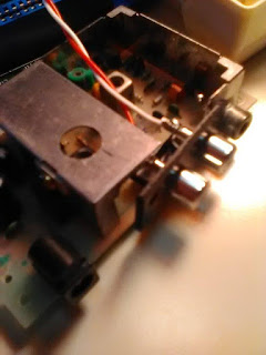
Using Metal Cutting Snips, or Dremel, cut out the metal shielding along your determined location markings.

As you can see in the photo I removed the front section of the shielding.
This makes removal of the RF components a little easier (Next step).
If you are planning to use the Famicom's original RF connector for the video out (as I have done) then simply unsolder the center of the RF pin from the PCB and bend it up and away from the PCB and then add a dab of solder to that pin.

====================
Step 3: RF Component Removal.
Tools Needed:
1. Soldering Iron.
2. Solder sucker/ Desoldering pump and Desolding Braid.
3. Needle Nose Pliers.
----------
-----
ADVISORY:
The components on the outside of the shielding are the AC (Power) and should be left alone.
The AC components needed are the 7805 Regulator, 1000uF Capacitor and one or 2 other components (possibly a fuse) depending on which Famicom generation board you're using.
-----
Flip the AC/RF board over and start removing the RF components from the PCB (Everything within the metal shielding) that may be in the way of shorting or preventing the RCA connectors from fitting within your hollowed-out shielding mount.
Here are some photos of the components I removed and their locations on the PCB.


====================
Step 4: RCA wiring.
Tools Needed:
1. Soldering Iron
2. Solder.
Parts Needed:
1. Cable/Wire.
2. RCA/AV Connectors.
----------
If your RCA jacks are color coded then this step will be simple.
Otherwise determine which connector you want to be White, Red, and Yellow (My yellow is the Famicom's RF jack).


Also:
As a little extra precautionary safety; You may want to use some electrical taper over the Ground pins of the AV connectors.
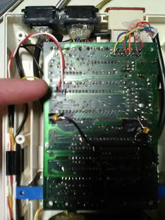
Here are some photos of the components I removed and their locations on the PCB.

Everything within the black circle are components I removed to make room for the connectors.

Side Note:
Ignore the black vertical lines (What looks like a # mark) on the PCB itself.
They were for my own reference as to component positions and solder points.
====================
Step 4: RCA wiring.
Tools Needed:
1. Soldering Iron
2. Solder.
Parts Needed:
1. Cable/Wire.
2. RCA/AV Connectors.
----------
If your RCA jacks are color coded then this step will be simple.
Otherwise determine which connector you want to be White, Red, and Yellow (My yellow is the Famicom's RF jack).
Side Note:
I used the inner insulated cable from an old A/V cable.
Once you have determined which RCA jack and color cable; it's time to solder the cable to the center pin of the connectors.

Once you have the Red and White cables secured to the center pins flip the connectors over and run a jumper piece of cable from both ground pins.

Now run another length of cable off one of the ground pins.
This extra length of cable will then be soldered to ground on the PCB.
Side Note:
I, lightly, twisted the Red and White cables and then held them together using a bit of electrical tape at the end.

Also:
As a little extra precautionary safety; You may want to use some electrical taper over the Ground pins of the AV connectors.
====================
Step 5: Mounting the AV connectors and Case Modification.
Tools Needed:
1. Soldering Iron.
2. Solder.
3. Hot Glue
4. Razor Blade.
Optional Tools:
1. Dremel with cutting blade
2. Needle Files.
----------


Step 5: Mounting the AV connectors and Case Modification.
Tools Needed:
1. Soldering Iron.
2. Solder.
3. Hot Glue
4. Razor Blade.
Optional Tools:
1. Dremel with cutting blade
2. Needle Files.
----------
Position the A/V connectors into place (Dry/Test fit).
Make sure the pins have enough clearance and are not touching the metal shielding or any other components. Also. Be sure they are not too close to the Famicom's RF jack as this may cause problems later when trying to hook-up the A/V cable.
Make sure the pins have enough clearance and are not touching the metal shielding or any other components. Also. Be sure they are not too close to the Famicom's RF jack as this may cause problems later when trying to hook-up the A/V cable.

If everything looks good then you are ready to solder the ground wire onto any grounding surface.
Side Note:
Technically the entire shielding is grounded so you could solder it to one of the walls.
However. I found a ground trace on the PCB.

Also:
The RF connector is already grounded through the same trace.
Now that we have the grounding for the AV connectors it's time to secure the rest of the connectors into place.
Simply place a few dabs of hot glue around the edge of the AV or Shielding and quicking, and accurately, place the AV connectors into place.
If everything is aligned correcting then continue around the edges of the AV connectors, securing it in place with more hot glue.

At this time you may now connect the Video cable to the origin RF connector's center pin.

And to keep everything tidy and neat,gently, twist the video cable into the audio cables.


----------
Case Modification:
At this point we will need to put the boards back into the top half of the Famicom housing/case.
The case does not accommodate our AV connectors, so we will need to modify the housing/case.
You can get technical here if you want and do precise measurements so that the case accommodates the new AV connectors.
Or you can mark out a general location and then cut out what isn't need on the case.
Side Note:
There is very little modification to be done to the red bottom of the Famicom housing, most of the cutting away will be done to the white top half.
====================
Step 6: Completing the Circuit.
Tools Needed:
1. Solding Iron.
2. Solder.
Optional Tools:
1. Electrical Tape.
----------
At this point you may want to determine the best course of routing your new cables within the Famicom's housing. Place the PCBs inside the top half of the Famicom shell and run the cables in various ways with the ends of the cables leading, what will be, their new solder positions.
Once you are satisfied solder the Audo and Video cables to their locations on the main PCB.
Side Note:
The AV mod tutorial does not make your Famicom True stereo.
It simply mimics it by having both speakers utilize the mono output through splitting it into both speakers (Red and White).
Here is an alternative method that will make use of the extra sound wave output, and giving true stereo.

The only downside is that, although it still functions for the system and games that utilize it, the speaker on controller 2 will not be broadcast to the TV speakers since this method uses pre-mix of the sound.
Also:
There is no need for a 220uF cap to be placed anywhere on the line when using this method.
Simply run the line directly to the output connector.
====================
Step 7: Famicom Assembly.
Tools Needed:
1. Phillips Screwdriver.
Place the Famicom PCBs back into position of the Famicom case.
Being careful not to pinch any of the extra cables, run them along your determined path.
Secure the boards and close of the case.
You are now ready to enjoy your Famicom through AV.
